Technical drawings can be very valuable sources of information if you know how to get the information from them. On the surface, the plans you are analyzing might seem like just lines and shapes on paper. You need to have the proper tool for reading those lines and shapes. This is where an engineering scale is valuable.
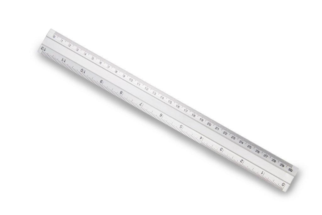
An engineering scale is basically an advanced ruler designed for determining linear measurements in technical drawings. It is a very common tool used for measuring things in land development and site construction plans.
Just like a standard ruler that is 12 inches long, a standard engineering scale (also 12 inches long) also has six edges used for measuring. A standard ruler usually has only two edges with which to measure. One edge of a standard ruler would be for measuring things in inches and the other edge might be for measuring things in a different unit such as centimeters.
Each of the edges of an engineering scale may be used for measuring different plans but all of the edges are used to measure things using the same units (usually feet). The actual edge that is used will depend on the drawing scale that was used to create the plan you are measuring.
Looking at a scale from either of the two long ends, you would see the shape of a three-point star. Along each side of each point of the star shape would be two of the six measuring edges of the scale.
Why Use an Engineering Scale?
In the creation of technical drawings (land development plans in particular), the design engineer or draftsperson has to pick a drawing scale to be able to display the plan in a form that is easily readable on the plan sheet of the chosen size.
This form, as an example, could be plan sheets that are 24 inches wide by 36 inches wide. If the plans being created involve areas greater than the plan sheet size, the area of the plan to be shown on the plan sheets would have to be reduced to a certain scale so that the entire area can be shown on the same plan sheet.
Common plan sheet scales include: one inch equals ten feet (1″=10′), one inch equals 20 feet (1″=20″), one inch equals 30 feet (1″=30″), one inch equals 40 feet (1″=40′), one inch equals 50 feet (1″=50′), and one inch equals 60 feet (1″=60″). These also happen to be the scales for which a standard engineering scale can be used to measure a plan. There is one corresponding drawing scale for each edge of the engineering scale.
At the far left side of each edge you will normally see one of the following numbers: 10, 20, 30, 40, 50, or 60. These numbers tell you the drawing scale for which you can use that edge to measure something off of a plan. For example, the edge with the number 40 would be used to measure things on a plan with a drawing scale of one inch equals 40 feet (1″=40′).
On the edge with a 10 (for a standard engineering scale), there are 12 major tick marks labeled 1 through 12. This is similar to a standard ruler except that with the engineering scale, the space between each major tick mark would normally represent 10 feet instead of just one inch. The minor tick marks between the major tick marks would represent one foot.
For the rest of the edges, the space between each major tick mark still represents 10 feet and the space between each minor tick mark still represents one foot. However, as the scale number increases, the number of major tick marks on the engineering scale increases since one inch equals a larger number of feet.
The main alternative to using an engineering scale to take measurements off of a plan would be to measure everything in inches using a standard ruler and then convert your measurements based on the drawing scale of the drawing.
For example, if you measure a distance from a plan with a drawing scale of one inch equals 20 feet (1″=20′) and your measurement is ten inches, the actual distance would have to be calculated to be 200 feet. The 200 feet equals 10 times 20 feet (20 feet for every one inch of measurement using the standard ruler). Using an engineering scale would make things a lot easier and more efficient especially if you plan on taking many measurements at a time.
Advertisement
Who Uses an Engineering Scale?
An engineering scale would be used by anyone wanting to take measurements on a plan that has a known scale.
Here are some examples of people who would use an engineering scale.
1) A land surveyor or design engineer might use an engineering scale to take measurements on a plotted plan to check their work.
2) A review engineer would want to have an engineering scale available any time there is work to be done involving the review of land development plans.
3) A local municipality (through a planning commission for example) might see a need to use an engineering scale to help with better understanding its evaluation of a set of plans brought to its attention at a meeting.
4) A contractor with a set of construction plans might have to use an engineering scale to determine construction materials quantities required for calculating construction cost estimates.
5) An individual homeowner who has a survey of their property created for their own use could use an engineering scale to take their own measurements from their survey plan.
An Engineering Scale Can Be Used for More Than Just Measuring Distances and Dimensions
The following are just some examples of things that can be measured from a plan using an engineering scale.
1) Property boundary dimensions.
2) General distances from structures to property boundaries or to other structures.
3) Roadway and driveway widths.
4) Areas of buildings, parking lots, wooded areas, or bodies of water (by using the engineering scale to measure shapes and doing some basic math).
5) Lengths of stormwater conveyance pipes, sanitary line pipes, and water supply pipes.
6) Earth excavation volumes required for construction assuming the plan contains topographic map information (by figuring out areas and doing some basic math).
How to Use an Engineering Scale to Measure Things Off of a Plan
Here are four simple steps to properly use an engineering scale.
1) Find the drawing scale of the plan you want to measure. You can determine this from a written label found within the title block of the plan or within the graphic scale that should be located somewhere on the plan along one of the sides.
2) Find the edge of your engineer scale that corresponds to the drawing scale you just found.
3) Take the measurement and read the number of your measurement off of your scale.
4) Multiply the scale measurement by 10 to obtain the actual measurement.
For example, if you are measuring something that is 50 feet long on a plan with a drawing scale of one inch equals 50 feet (1″=50′), your engineering scale would show the number 5. If you are measuring something that is 54 feet long on a plan with a drawing scale of one inch equals 50 (1″=50′), your engineering scale would measure that something at 4 minor ticks marks past the number 5. Since there are 10 minor tick marks between major tick marks, your scale measurement would be 5.4 which you would then multiply by 10 to get 54 feet.
Note that sometimes you might have a plan with a drawing scale that is beyond one inch equals 60 feet (1″=60″) such as one inch equals 200 feet (1″=200′). In this example, since 200 is a multiple of 20 (by a factor of 10), you would just use the 20-scale edge of your engineering scale and multiply your measurement number by 100.
There could also be times when you have a plan with a drawing scale that is less than one inch equals 10 feet (1″=10″) such as one inch equals five feet (1″=5′). In this example, your scale measurement would be your actual measurement without having to multiply anything.
Advertisement
Consider Getting Yourself an Engineering Scale
If you plan on taking any kind of measurements from technical drawings on a regular basis (even just to check dimensions on a plan of your own property), you should consider purchasing an engineering scale.
An engineering scale is relatively inexpensive and it will save you a lot of extra effort (and extra math) when measuring things from your plans.


